 |
 |

|
||
| Vacuum
creating systems 1) based on vacuum hydrocirculating units 2) based on steam ejectors |
||
|
Jet compression units for flare and low-pressure gases recovery 1) based on two-phase jet devices 2) based on steam ejectors | ||
| Jet
absorption gas cleaning units for hydrocarbons removal from breathing gases and oil and petroleum products gases recovery |
||
| Jet
devices ejectors and injectors for various purposes |
 |
|
Technovacuum Ltd. +7 (495) 956-76-21 +7 (499) 261-99-98 +7 (499) 267-82-03 Russia, 105082, Moscow B.Pochtovaya str., 26 "B", build.2, 5-th floor, office 1, room 11A |
||
JET ABSORPTION
GAS CLEANING UNITS
|
 |
 |
 |
At present the oil industry uses various methods to reduce the loss of oil products by recovery of breathing gases. It is the recovery systems for light hydrocarbon fractions that are currently considered as the most promising and can radically increase the environmental and economical levels of all production operations connected with intake, storage and distribution of crude oil and petroleum products.
There are several methods of breathing gases cleaning from hydrocarbons, among which the adsorption-absorption method and the method using membrane technology are the most known.
Technovacuum Ltd. offers its new technology based on jet systems
– a jet absorption unit for breathing gases cleaning and recovery of oil and petroleum products gases at loading
racks, terminals and tank batteries.
Layout of jet absorption unit
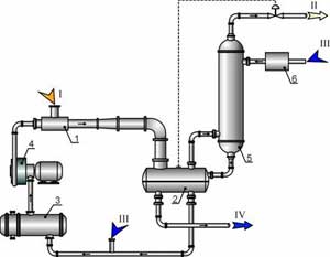 |
1 – liquid-gas jet device 2 – separator 3 – heat exchanger (if necessary) 4 – pump 5 – absorber 6 – chilling unit I – air-vapor mixture II – purified air III – fresh motive liquid IV – excess of motive liquid |
Principle of jet absorption unit operation (for gasoline loading racks)
The air-vapor mixture (I) from the gasoline loading rack is delivered to the inlet of the jet device 1. Gasoline delivered by the pump 4 is used as a motive liquid in the jet device. As a result of ejection process, compression of the air-vapor mixture and absorption of gasoline vapor by motive liquid occur in the jet device 1.
The gas-liquid mixture is delivered from the jet device 1 to the separator 2, where the further absorption of gasoline vapors by motive liquid and air separation occurs. The final purification of air from hydrocarbon vapors is carried out in the absorber 5, where the gasoline cooled in the chilling unit 6 is delivered as an absorbent. The purified air being free of hydrocarbons (II) is vented from the absorber 5 to atmosphere.
Up to 99% of hydrocarbons is extracted from a gas-vapor flow entering the jet absorption unit. The pressure in the absorber 5 is maintained due to a control valve installed in the line for gas discharge from the jet absorption unit. The circulating motive liquid is delivered from the separator 2 to the heat exchanger 3 (is installed if necessary) for cooling, and then it is delivered to the suction of the pump 4. Makeup (III) with fresh gasoline for refreshment of the motive liquid is provided. Excess of the motive liquid (IV) is discharged from the unit to the loading rack or to the tank battery via a level control valve of the separator 2.
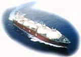
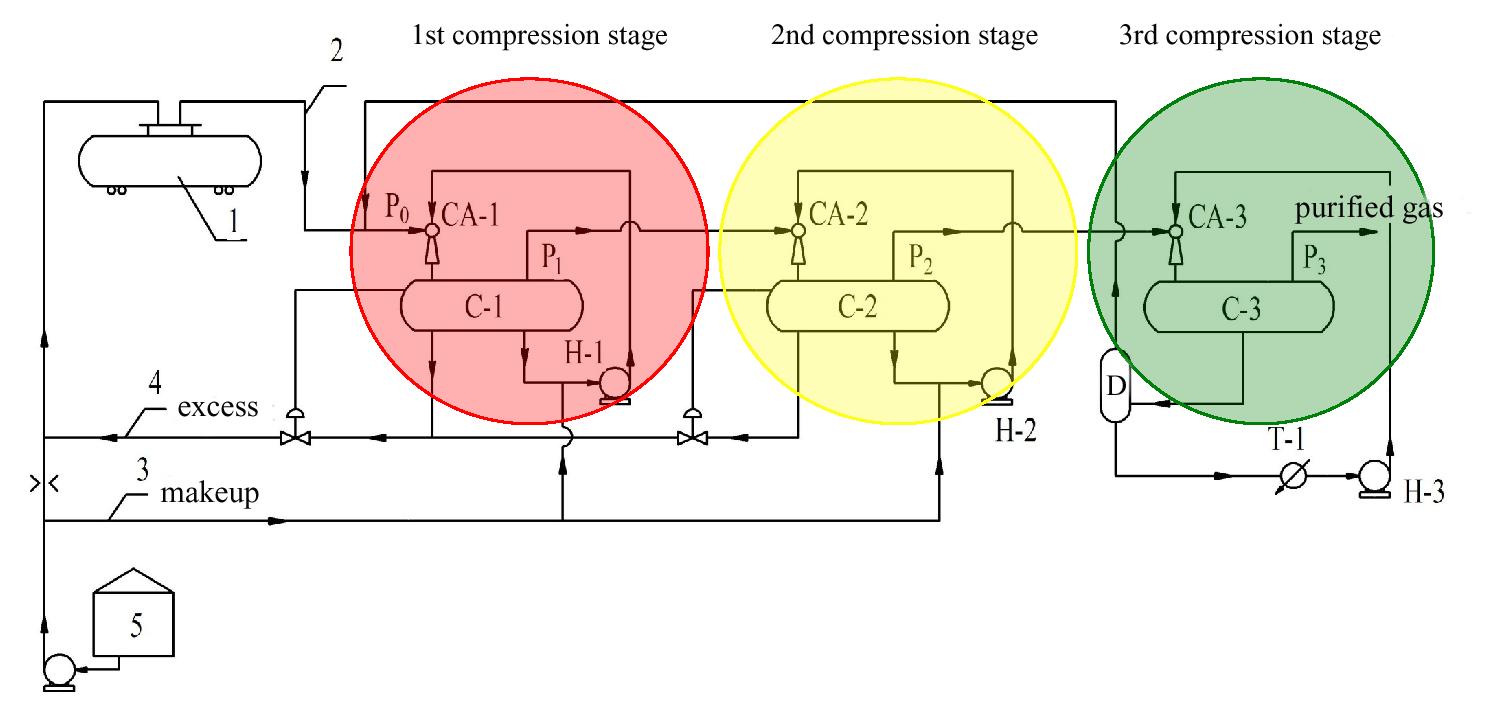
Jet absorption unit for oil vapor recovery
The unit is intended for recovery of oil vapor (light hydrocarbons) from breathing gases generated during oil loading into tankers or railway tanks.
This jet absorption unit ensures high efficiency of breathing gas purification (more than 95%) from oil vapor at any content of sulfur compounds (H2S, methylmercaptane etc.).
For example, similar systems of other firms use carbon adsorbers which can’t provide cleaning efficiency higher than 85% (excluding methane). Such adsorbers can’t clean breathing gases from methane.
Also they have low efficiency of breathing gases cleaning from ethane.
Moreover, the systems that use carbon adsorbers have the strict limitation for hydrogen sulfide concentration in breathing gases. It should be less than 20 ppm because higher H2S
concentrations cause pollution of carbon adsorbers by sulfide which cannot be removed during the process of the adsorber regeneration. To reach H2S concentration in breathing gases
of 20 ppm or less, the crude oil should have hydrogen sulfide concentration less than 1.0 ppm. If oil with 20 ppm H2S concentration is poured, H2S
content in breathing gas is more than 1000 ppm. Some crude oils may have H2S concentration up to 100 ppm.
Jet absorption unit for oil vapor recovery offered by Technovacuum Ltd. has no analogues around the world and is covered by a number of patents.
Major advantages of jet absorption system offered by Technovacuum Ltd. in comparison with similar systems of other firms are the following:
 |
If you are interested in the technology of jet absorption gas cleaning
units for removal of hydrocarbons from tank breathing gases of loading
racks, terminals and tank batteries and you plan to introduce it at your
enterprise, please, fill in the following
Questionnaire for jet absorption unit of loading rack.
Questionnaire for jet
absorption unit of tank battery.