 |
 |

|
||
| Vacuum
creating systems 1) based on vacuum hydrocirculating units 2) based on steam ejectors |
||
|
Jet compression units for flare and low-pressure gases recovery 1) based on two-phase jet devices 2) based on steam ejectors | ||
| Jet
absorption gas cleaning units for hydrocarbons removal from breathing gases and oil and petroleum products gases recovery of |
||
| Jet
devices ejectors and injectors for various purposes |
 |
|
Technovacuum Ltd. +7 (495) 956-76-21 +7 (499) 261-99-98 +7 (499) 267-82-03 Russia, 105082, Moscow B.Pochtovaya str., 26 "B", build.2, 5-th floor, office 1, room 11A |
||
1) VACUUM CREATING
SYSTEMS
|
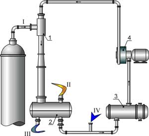 |
1 – vacuum creating device 2 - separator 3 - heat exchanger 4 - pump I - gas-vapor mixture from vacuumized vessel II – compressed gas outlet line III – motive liquid excess withdrawal line IV – fresh motive liquid makeup line |
Principle of operation
The pumped-out medium is delivered from technological device, e.g. a distillation column, to inlet of the vacuum creating device 1. In the vacuum creating device 1 the gas-vapor mixture is compressed due to energy of the motive liquid jet supplied to the device 1 by the pump 4. One of the process flows, which is allowed to mix with vapor evacuated by the vacuum creating device, can be used as a motive liquid.
In oil refining a diesel fraction or vacuum gas oil is used as the motive liquid. In the caprolactam production the motive liquid is a cyclohexanol-cyclohexanone mixture.
Along with gas-vapor compression the process of vapors condensation on the jet of motive liquid occurs. In this case vapor condensation and gas cooling in the vacuum creating device occurs along the isobar and their compression to the discharge pressure - along the isotherm. It makes the device energy-efficient in comparison with other vacuum pumps, especially in the case of pumping gas-vapor mixtures with a high percentage of vapor.
The generated gas-vapor mixture goes from the vacuum creating device 1 to the separator 2, where gas and liquid separation occurs. The gas compressed to the required pressure is sent for further recycling, e.g. for combustion. After the removal of heat excess in the heat exchanger 3, the motive liquid is delivered to the vacuum creating device 1 by the pump 4. If necessary, the makeup is carried out to refresh the motive liquid. The balance excess of the motive liquid is withdrawn from the system.
Main advantages of VHC unit
The advantages of vacuum creating systems based on the vacuum hydrocirculating unit are given below as compared with
steam ejectors:
mechanical vacuum pumps:
liquid ring vacuum pumps:
After a slight modification VHC unit can operate as a compressor that compresses various gases
and gas-vapor mixtures including polluted and explosive ones.
Other VHC unit application layouts for vacuum creation in columns of refineries
There are various possible layouts of VHC units depending on required capacity, vacuum level, compression ratio, evacuated gas-vapor mixture composition, column operating conditions, equipment layout, Customer requirements and other factors.
Layout of the two-stage VHC unit with hydrocarbon motive liquid;
Layout of the two-stage VHC unit with steam and liquid circulation loops
(for creating stable high vacuum of 15-25 mm Hg in refinery vacuum columns and reduction of electric energy consumption);
Layout of the VHC unit with chiller;
Layout of the VHC unit with motive liquid regeneration and hydrogen sulfide removal.
Industrial application experience
For the first time in world practice the VHC unit was introduced at the distillation column VK-1 of Atmospheric-vacuum distillation unit-3 (AVT-3) of Moscow refinery in 1993.
By the beginning of 2023, Technovacuum Ltd. has more than 60 implementations of vacuum creating systems based on VHC unit at vacuum columns of oil refineries, chemical and petrochemical plants in Russia and other countries.
The implementation of vacuum creating systems based on VHC unit at these plants resulted in considerable energy savings, reduction of waste water treatment costs and increased product yield due to holding a stable vacuum level in column.
Based on field experience of VHC units, increase in product yield reaches up to a value of 1.5 %. The payback period of vacuum creating systems revamping is therefore 4-18 months, depending on energy and oil products prices.
In oil-refining industry VHC units are used for vacuum creation in crude distillation units. In chemical and petrochemical industry they are used in units for cyclohexanol-cyclohexanone, alkylbenzene, benzene-toluene-xylene fraction production and other.
Features of VHC units performance characteristics
Accepted notation of VHC units
Notation example: VHC-140-2-V-1 (the picture of VHC-140-2-V-1 of Atmospheric vacuum distillation unit-4 (AVT-4) of Ufaneftekhim OJSC)
Description of the VHC unit notation:
| VHC | vacuum hydrocirculating |
| 140 | capacity, m3/min |
| 2 | minimum suction pressure, kPa |
| V | V – air-cooling (А - water-cooling) |
| 1 | serial number of design modification version |
The capacity range of the industrial VHC units is 20 m3/min - 350 m3/min. Capacity of VHC units is indicated for dry air at temperature 20 оC.
Technovacuum Ltd. constantly improves the VHC units in order to reduce power
consumption and decrease the suction pressure.
Equipment layout solutions
The VHC units are easily mounted both at new and existing columns.
Layout of the VHC unit on the existing platform (column K-1 of bitumen unit of Mozyr Refinery).
If you are interested in vacuum creation technology based on VHC
unit and you plan to apply it at your enterprise, please fill in the
following
Purpose
Steam ejectors have been used for vacuum creation in technological vessels for about two centuries. Due to technical characteristics of these devices, multi-stage steam vacuum creating systems with inter-stage surface condensers are mostly used.Layout of three-stage vacuum creating system based on steam ejectors
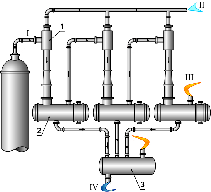 |
1 - steam ejector 2 - condenser 3 - separator I - gas-vapor mixture from vacuumized vessel II - active steam III - compressed gas outlet line IV – condensate outlet line |
Main advantages:
Disadvantages in comparison with VHC units: